Someone recently showed me the Web SDR (Software Defined Radio) site from the University of Twente, and asked how it was possible that 200 people could be listening to different frequencies all at once from a single radio board. It seems counterintuitive, since a conventional radio adjusts a tuner circuit to pick up a given frequency. Since the board doesn’t have 200 different tuners, how can so many users listen to different stations?
Conventional radio
One of the simplest ways of transmitting a signal by radio is to use Amplitude Modulation (AM), where the signal is summed with a high frequency carrier wave before transmission. The signal can be anything from voice to Morse code, or even music or data. To receive the signal, you need to tune a circuit to the frequency of the carrier wave, and use a low pass filter to remove the carrier. What you’re left with is the original signal.
Image by Berserkerus, CC BY-SA 2.5, via Wikimedia Commons
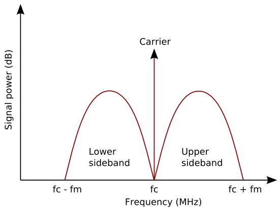
In the frequency domain, an AM transmission looks like a central spike for the carrier wave frequency, with groups of smaller components just above and below the carrier. These sidebands contain all the information from the original signal.
Multiple stations can transmit simultaneously by using different carrier frequencies. Stations need to be spaced far enough apart that the sidebands don’t overlap. That is, the highest frequency of one station mustn’t overlap with the lowest frequency of another, otherwise you’ll hear both stations at the same time when tuned to one.
Shortwave radio typically uses amplitude modulation for voice and Morse code transmissions. The shortwave band is 1.6MHz to 30MHz, and channel spacing can be 5kHz or 10kHz. Assuming the narrowest spacing, that means the shortwave band can accomodate simultaneous transmissions without interference. Each listener is completely unaware of the other transmissions, because their receiver is tuned to the carrier frequency of a single channel, and the circuit only responds to a narrow band of spectrum around that one frequency.
Web SDR
The University site allows multiple users to simultaneously listen to different channels, and in fact view the entire shortwave spectrum as a waterfall plot. Conventionally, this would require 5680 separate tuners all tuned to a different channel. But the image at the top of the page shows a single, smallish board. The components (described on the board designer’s site) are an antenna, the tuner circuit, an analogue to digital converter (ADC), an FPGA, another IC, then an ethernet port. So what’s happening here?
Image by PA3FWM
The key is the ADC. It doesn’t operate continuously, but takes regular snapshots of its analogue input, spitting out the equivalent digital value at a certain speed. If it’s taking input from a single tuner tuned to one frequency, the speed that it needs to snapshot the analogue signal at must be equal to or greater than twice the highest data frequency in the channel (the Nyquist frequency).
If the ADC can operate much faster than the required sampling rate for one channel, there’s enough time to progressively tune the tuner to the next band and take a snapshot of it, then tune to the next band and snapshot it, and so on, covering a whole block of spectrum before cycling back to the start again.
If the data in the channel is something like Morse code or voice, the sampling rate can be fairly low. To take a really simple example, say a 50Hz tone is being transmitted on a carrier wave of 10MHz. You only need to sample at twice the tone frequency to reconstruct the “information” exactly (i.e. sampling the combined 50Hz + 10MHz signal at a rate of 100Hz will allow you to reconstruct the 50Hz tone exactly). A human voice can cover a very wide frequency spectrum, but it only needs about 3kHz to sound normal, therefore needing a sampling rate of 6kHz. Given a channel spacing of 5kHz, if that entire space were filled, a sampling rate of 10kHz is needed to reconstruct the signal.
The board website says the ADC used is the LTC2208, which has a maximum sampling rate of 130MHz. Assuming a rate of 10kHz per channel, that allows 13,000 channels to be sampled without data loss! The latest version of the board uses a sampling rate of 77.76MHz, giving channels, which is well above the needed 5680 calculated above.
Coping with the data rate
As may be expected, this generates a lot of data. 16 bit values sampled from 5680 channels 10,000 times per second gives 108MB of data every second, or 380GB per hour. This needs to be transferred off the board, and served over the internet.
The board originally used the ATmega32 microcontroller, which is an 8-bit chip clocked at 16MHz. This takes the output of the ADC and converts it into ethernet packets (10Mbit/s for this earlier version of the board). However, the data speed was so high that some corners had to be cut in encoding the ethernet packets (specifically, the CRC field was just filled with garbage).
Later versions switched to using an FPGA instead of a microcontroller, and external chips were used for ethernet encoding, to cope with the data rate. The University version of the board also uses an FPGA instead of a microcontroller, and chips for Gigabit ethernet instead of 10Mbit/s.
Delayed decode
The calculations here show that it’s possible to use a single tuner and ADC to sample all possible channels in the shortwave band without data loss. It relies on an ADC which can operate at 56.8MHz or above, and a tuner circuit which can switch frequency fast enough to match the ADC speed. It also requires enough data throughput to get the channel data off the board and onto a computer for further processing.
Since the board itself isn’t doing any decoding or interpretation of the signal, it’s up to the computer to convert the raw spectrum energy values into data. This has one really neat side effect: you can record an hour of the full raw spectrum, and later go back to listen to any frequency within it. The practical benefit of this is that you don’t have to know beforehand how to interpret a signal. Different transmitters use different encoding schemes (such as single sideband to boost signal power), and with a recording you can try various decoding approaches until you find the right one. Then you can replay the entire transmission from the start, and listen to historical messages.
And if you’ve never listened to shortwave radio before, go to the University site right now and tune to frequency 4625kHz. This is UVB-76, a Russian not-quite numbers station which transmits continuously. If you’re lucky, you’ll hear a voice, too.